Voltage Sensor with Arduino – Measure up to 25V using Arduino
A Voltage Sensor is a simple module that can be used with Arduino (or any other microcontroller with input tolerance of 5V) to measure external voltages that are greater than its maximum acceptable value like 5V in case of Arduino.
Sensing the amount of current passing through any circuit can be useful in a lot of applications. For example, in low power-consuming equipment, current sensing will be helpful to understand the system’s impact on its battery life. The current sensing can also be used to make decisions regarding safety in over-current protection circuits.
Simply, we can say that sensing and controlling the flow of the current through the circuits is now a fundamental requirement e.g. overcurrent protection circuits, battery chargers, watt meters, power supplies etc.
* - VOLTAGE SENSOR
* PIN CONNECTIONS SENSOR
* S --> A3 green
* + --> 5V red
* - --> GND blue
* Calculate exact values with multimeter:
* Vin on adapter = 12.41V
* Vout on Arduino = 2.42
* 5V on Arduino = 5.10V
* Vin / vOut = factor
* 12.41 / 2.42 = 5.128
*/
const int voltageSensorPin = A3; // sensor pin
float vIn; // measured voltage (3.3V = max. 16.5V, 5V = max 25V)
float vOut;
float voltageSensorVal; // value on pin A3 (0 - 1023)
const float factor = 5.128; // reduction factor of the Voltage Sensor shield
const float vCC = 5.00; // Arduino input voltage (measurable by voltmeter)
void setup() {
Serial.begin(9600);
}
void loop() {
voltageSensorVal = analogRead(voltageSensorPin); // read the current sensor value (0 - 1023)
vOut = (voltageSensorVal / 1024) * vCC; // convert the value to the real voltage on the analog pin
vIn = vOut * factor; // convert the voltage on the source by multiplying with the factor
Serial.print("Voltage = ");
Serial.print(vIn);
Serial.println("V");
delay(1000);
}
Components Required
Arduino UNO
Voltage Sensor Module (for < 25V)
16×2 LCD Display
10KΩ Potentiometer
330Ω Resistor
Connecting Wires
Mini Breadboard
Circuit Design
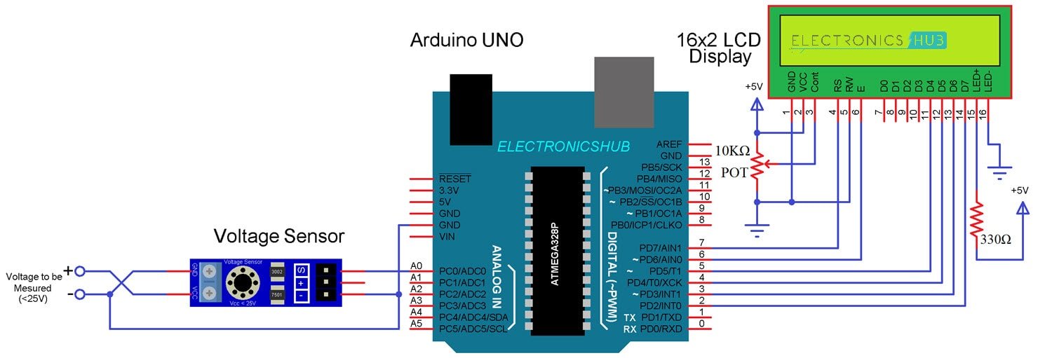
First, connect the “S” and “–” pins of the Voltage Sensor to A0 (Analog Input) and GND of Arduino respectively. Then connect the external voltage pins (voltage to be measured) to the screw terminal (check for polarity).
Coming to the LCD, Digital I/O Pins 7 and 6 of Arduino UNO are connected to RS and E while the Pins 5 through 2 of Arduino UNO are connected to D4 through D7 respectively.
If you want to Make your Own Voltage Sensor
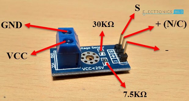
Using a pre-built voltage sensor module is very easy and if you don’t have one then you can easily build one yourself. All you need are two resistors.
If you want to make your own voltage sensor that can measure voltages up to 25V like this Voltage Sensor Module, then you have to get a 30KΩ and a 7.5KΩ resistor.
Interfacing a Voltage Sensor with Arduino
Now that we have seen a little about the Voltage Sensor, let us now proceed with Interfacing a Voltage Sensor with Arduino and measure some external voltages.
The Arduino Voltage Sensor Interface is pretty straightforward. Connect the voltage to be measured to the screw terminal of the Voltage Sensor, connect the output of the voltage divider to the Arduino. That’s it.
After interfacing the Voltage Sensor with Arduino, you can either view the results on the serial monitor of the Arduino IDE or on a 16×2 LCD Display. I have gone with the LCD Display.
The Voltage Sensor module is basically a voltage divider circuit, you can calculate input voltage using the formula
Vin = Vout * (R2/(R1+R2))
Here R1 = 30000, R2 = 7500 and Vout can be calculated from Analog Input of Arduino by using Vout = (analogvalue * 5 / 1024).
Code
#include "LiquidCrystal.h"
const int voltageSensor = A0;
float vOUT = 0.0;
float vIN = 0.0;
float R1 = 30000.0;
float R2 = 7500.0;
int value = 0;
LiquidCrystal lcd(7, 6, 5, 4, 3, 2); // RS, E, D4, D5, D6, D7
void setup()
{
//Serial.begin(9600);
lcd.begin(16,2);
lcd.print(" Measure > 25V ");
delay(2000);
}
void loop()
{
value = analogRead(voltageSensor);
vOUT = (value * 5.0) / 1024.0;
vIN = vOUT / (R2/(R1+R2));
//Serial.print("Input = ");
//Serial.println(vIN);
lcd.setCursor(0,0);
lcd.print("Input = ");
lcd.setCursor(9,0);
lcd.print(vIN);
delay(500);
}