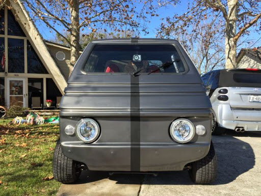
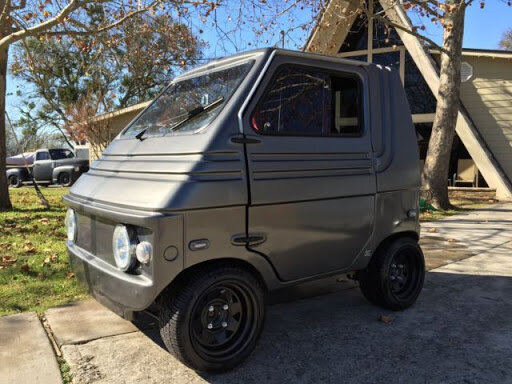
El Car Zele Zagato Electric Car Restoration 1974
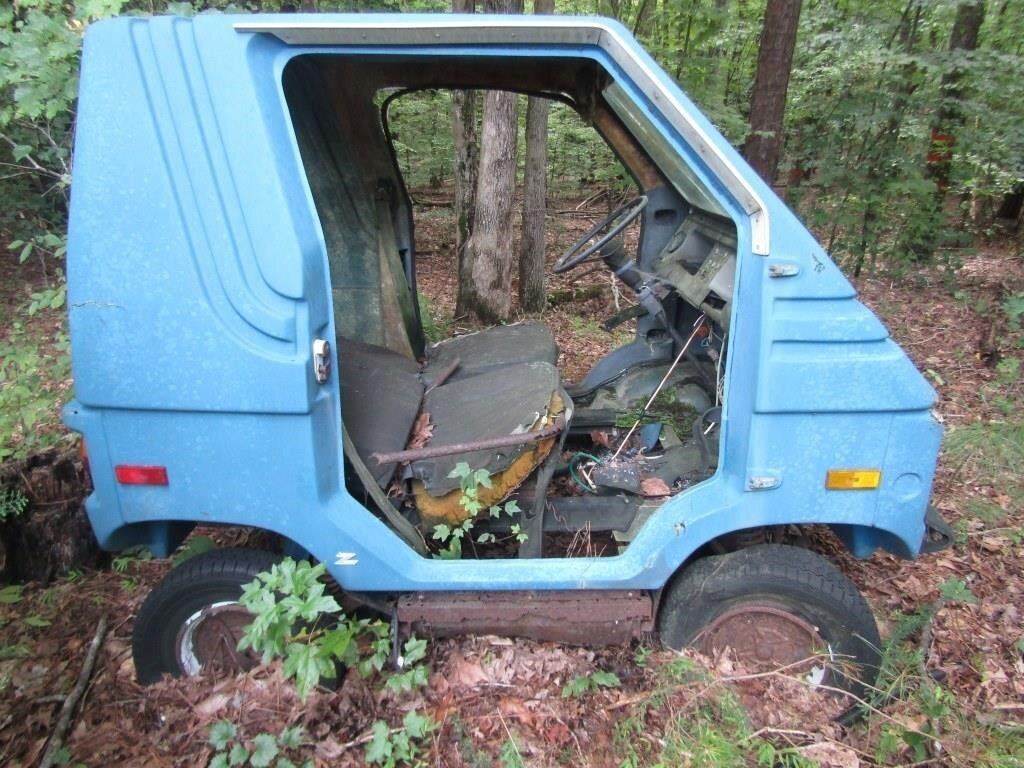
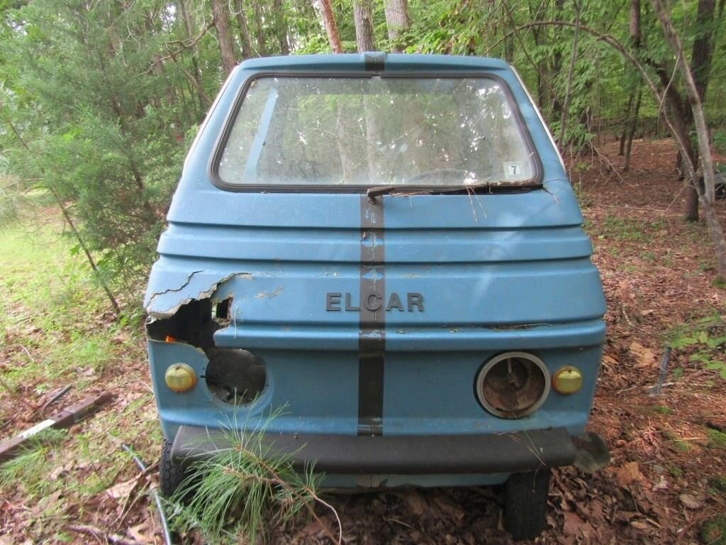
Byron and myself are rebuilding a 1974 Electric Car called the Zagat Zele or El Car. There was only 500 made and are very rare. We’ll have a complete playlist of the project , here’s a link to that. This was one of several vehicles that quickly appeared in the 1970s in response to the fuel crises. Zagato’s solution was a tiny electric car and they put this
This video explains how we found it in a forest.
ZAGATO ZELE (Called the El Car in States)
The Zagato Zele was a significant departure from the norm for Zagato, a coachbuilder and automaker better known for their impossibly sleek designs typically hand-crafted from aluminum alloy and gracing chassis made by the likes of Ferrari, Lamborghini, Alfa Romeo, Aston Martin, BMW, Lancia, Fiat, Isotta Fraschini, Jaguar, Bristol, and even a Shelby Mustang.
How it worked -
The batteries were originally wired as series/ parallel, max voltage at 48, 36 and 24 volt... the 24 got you going max
Current to field, then as speed caught up in magnetic flux the next solenoid jumped it to 36 volt and field voltage decreased through resistor one, then as speed again increased solenoid two kicked in and shunted the voltage through resistor two increasing the current for stronger field again.Its difficult to explain as I am not up on my electrical theory as I remember.
If the solenoids are replaced that would help greatly. There is only a coil that draws in a solid copper bar across two posts making contact.. arcing occurs and after awhile destroys the bar. These are easily replaceable.
State solenoids from old fords (1960s) or tractors that had inertia starters work best. These are starters once current is applied , torque hard enough to throw the gear on the twisted shaft into the flywheel. These solenoids are seperate on the old cars and trucks, they usually handle loads over 500 amp easily and are very cheap... under 20 bucks.
The three wires are field wires I think each wired in series to each other the wires are taps to first , second and third field . The control battery is seperate from the battery bank and powers the lights, and solenoid control .
As I said before......GOOD LUCK... I would read up as much as I could on electric cars from the 60s and 70s as they were basically wires similar.
If i find my folder on electric cars I will send it to you... it's fairly thick.. and informative.
Though the looks of the Zele often inspire jokes, the car was actually decades ahead of its time. Consider for a moment the startling similarity between the Zele and the Smart Car, which wouldn’t appear until decades later in 1998. It’s worth also noting that the Zele is 100% electric, and we didn’t see a 100% electric Smart Car until 2008.
Though the existence of the Zagato Zele is often linked to the 1973 Oil Crisis that drove gasoline prices up significantly around the world, the car was actually designed, built, and publicly shown a year before the crisis.
Zagato first displayed the Zele at the 1972 Geneva Motor Show where it was surrounded by many of the most beautiful cars of its era, and some of the most beautiful of all time. There’s little doubt that the humble Zele raised some eyebrows due to its looks, but less than 12 months later it would prove to have been the most sensible option at the whole show.
THE ZAGATO ZELE DRIVETRAIN AND ENGINEERING
The design team at Zagato had been tasked with creating the Zele from a blank slate, it needed to be created as cheaply as possible, and it needed an electric drivetrain.
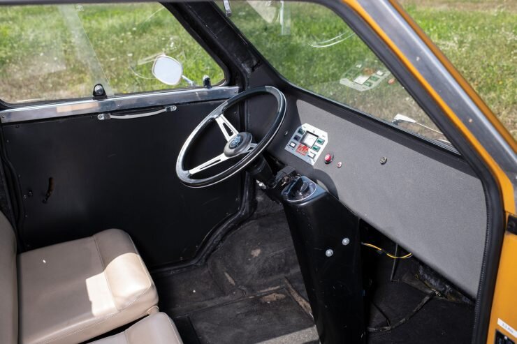
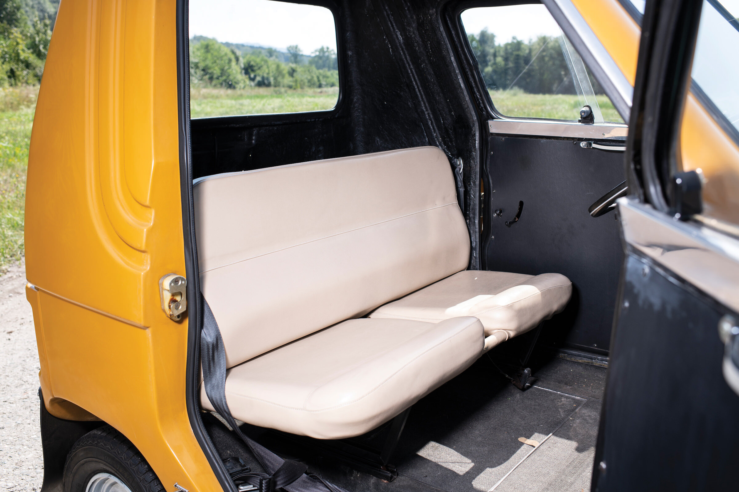
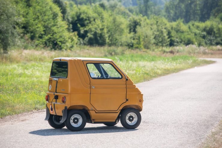
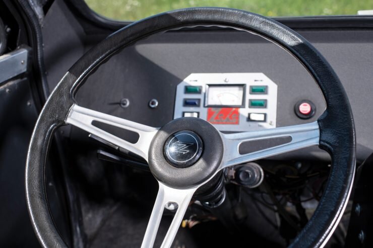
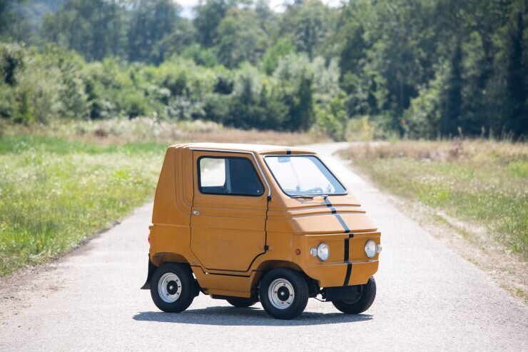
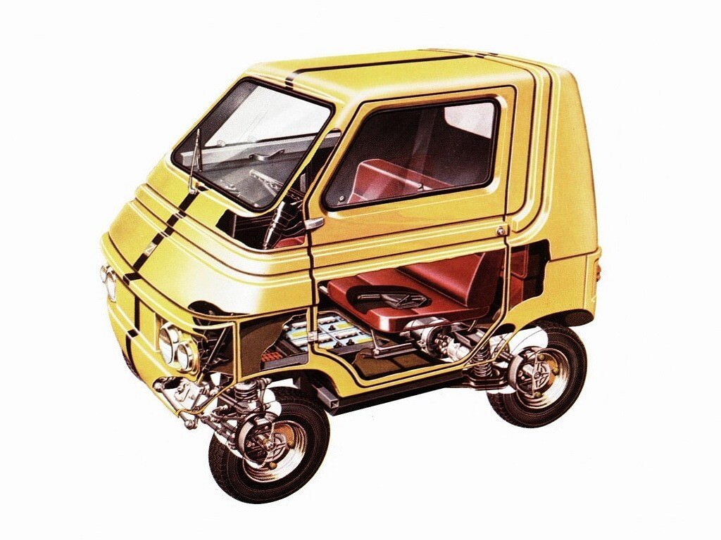
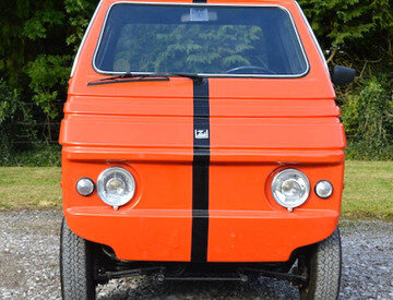
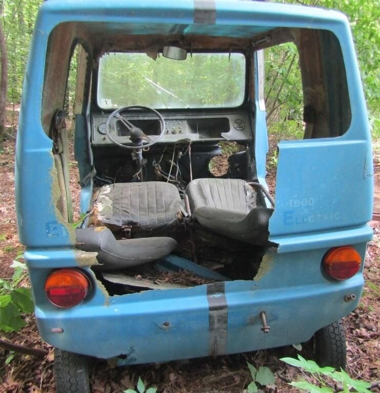
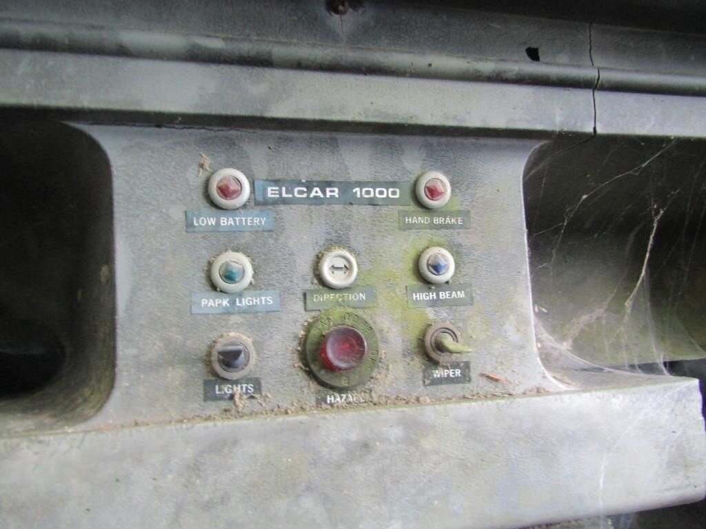
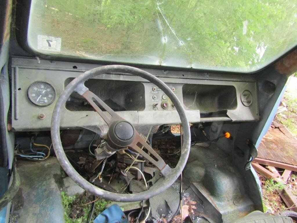
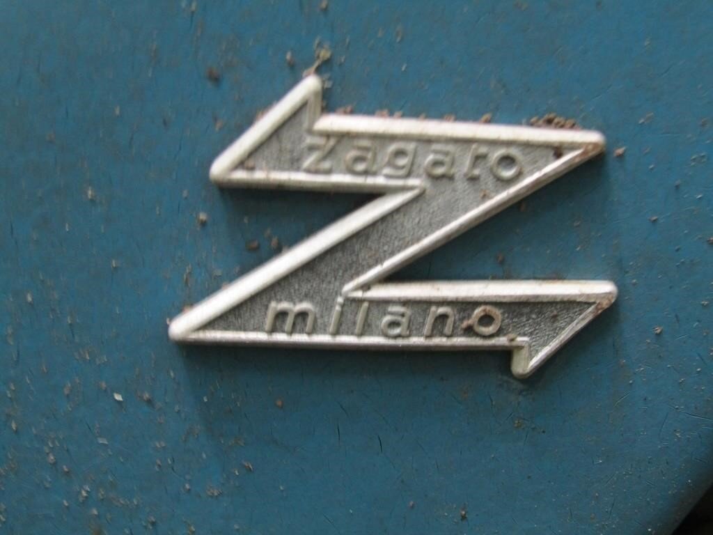
It was decided early on to use a lightweight fiberglass body over a simple steel frame, the running gear was sourced from the Fiat 500 and 124, and the interior was so spartan it qualifies as minimalist, with a bench seat, a flat dashboard, and a steering wheel emblazoned with the legendary Zagato “Z”.
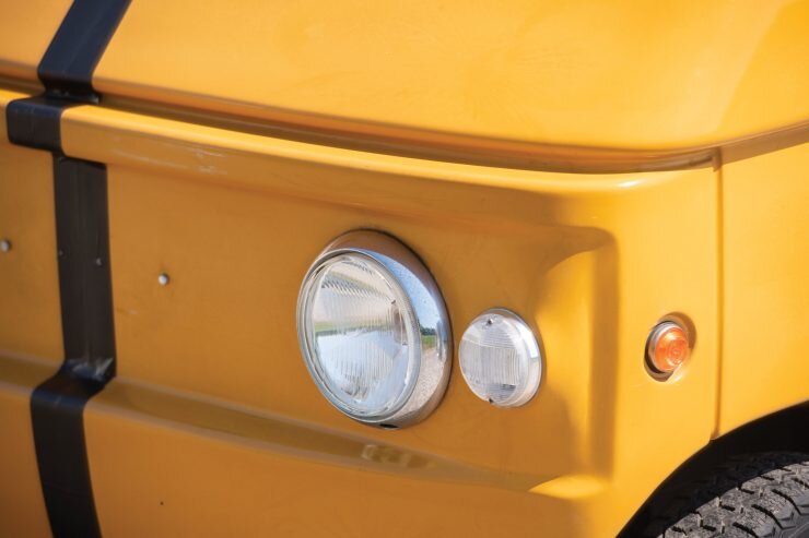
In order to keep costs down there are no wind down windows, just sliding units that’ll be familiar to vintage Land Rover owners. The windscreen is a flat pane of angled glass, the door hinges are external, and the headlight, indicators, and taillights are all sourced from a spare parts catalogue.
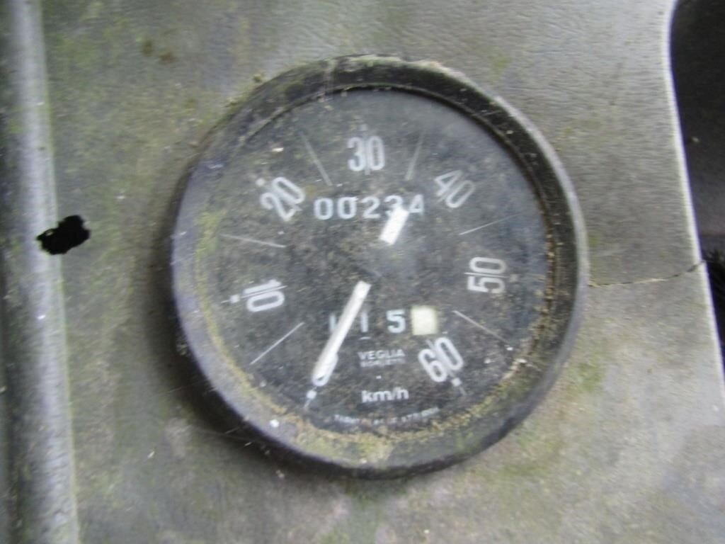
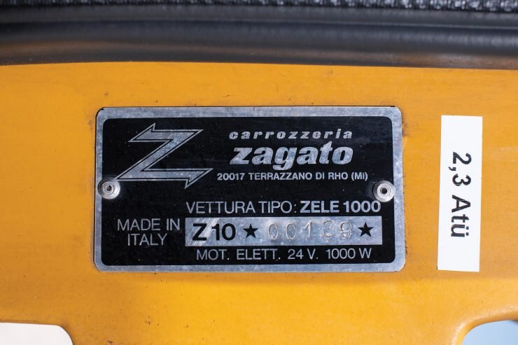
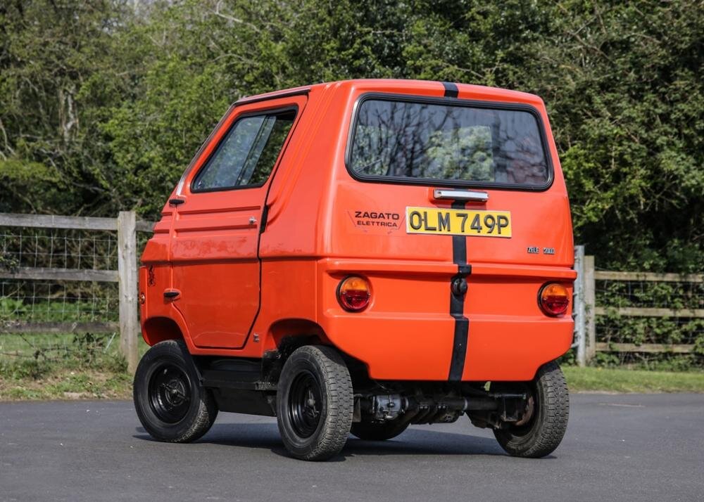
Electrical power is provided by four 12 volt car batteries producing 24 volts in total, these are connected to a 1000 watt Marelli direct drive electric motor. The top speed is claimed to be between 25 mph and 30 mph, and the range is 50 miles (80 kilometers), though this may not seem like far it’s considerably less than the average daily commute, and the Zele can be recharged by plugging in the rear-mounted cable directly into the mains.
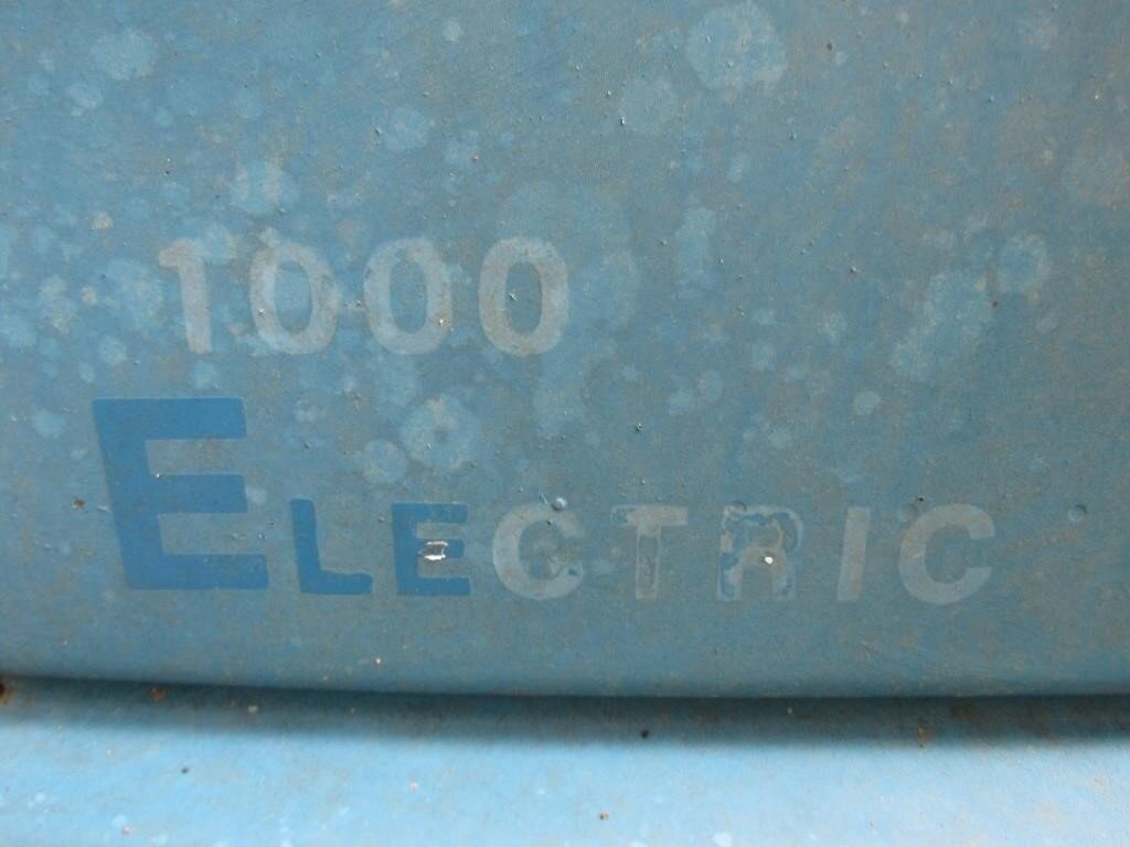
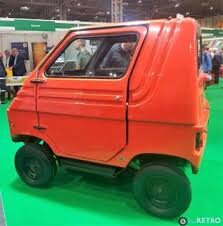
Despite its looks the Zele is relatively stable as the majority of its weight is in the frame and batteries – mounted down in the floor. Over the course of its relatively short production run the Zele, which was sold in the USA as the Elcar, was offered in 1000, 1500, and 2000 model designations, each referring to the wattage of the electric motor.
Zagato Zele (2000) specs
Car type Compact
Curb weight 520 kg (1146 lbs)
Dimensions1.95 m (77 in) long
Wheelbase1.30 m (51 in)
Years built 1973 - 1976 Origin country Italy
1972 Zagato Zele Golf Cart in Yuppies 2, Movie, 1986
Class: Others, Microcar — Model origin: Minor action vehicle or used in only a short scene

The Zagato Zele was also sold in the US market as the Elcar which had corporate headquarters based in Elkhart, IN. There were two, two passenger models available; Elcar 1000 and Elcar 2000. A running chassis was also available. There was a proposed Elcar 4000 (Wagonette), although only the prototype was known (four-passenger).
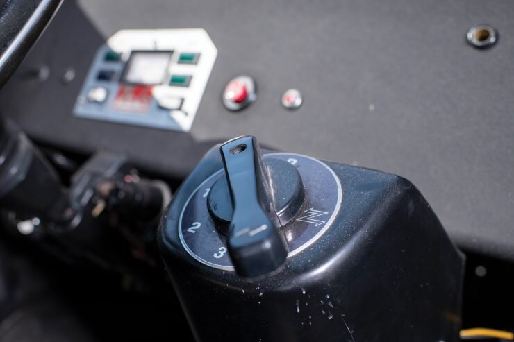
The motor works on a successive 24, 36 and 48 volts from a solenoid-operated speed control system (think of it as an " electric manual transmission").
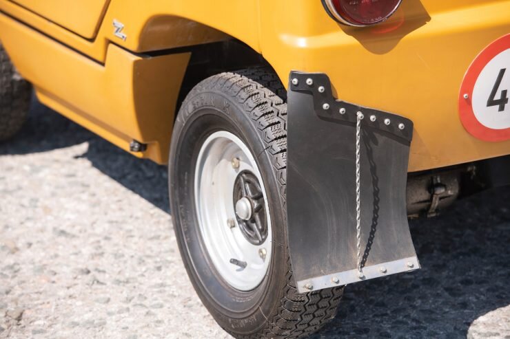
The vehicles had fiberglass bodies with front and rear drum brakes along with coil spring suspension front and rear. Much of the suspension and mechanicals were derived from the Fiat 500. Factory tyres were Michelin X2 145 SR10s.
How the Zele (El Car) Electric System worked
The batteries were originally wired as series/ parallel, max voltage at 48, 36 and 24 volt... the 24 got you going max Current to field, then as speed caught up in magnetic flux the next solenoid jumped it to 36 volt and field voltage decreased through resistor one, then as speed again increased solenoid two kicked in and shunted the voltage through resistor two increasing the current for stronger field again.
It’s difficult to explain as I am not up on my electrical theory as I remember.

The series 1000 had a 2 1/2 hp motor a top speed of 25 miles an hour but a range up to 50 miles between charges both models worked out the Solenoid operated speed control system feeding in successive stage is 24, 36 and 48 V to the motor from a pack of x8 12 Volt lead batteries
If the solenoids are replaced that would help greatly. There is only a coil that draws in a solid copper bar across two posts making contact.. arcing occurs and after awhile destroys the bar. These are easily replaceable.
State solenoids from old fords (1960s) or tractors that had inertia starters work best. These are starters once current is applied , torque hard enough to throw the gear on the twisted shaft into the flywheel. These solenoids are separate on the old cars and trucks, they usually handle loads over 500 amp easily and are very cheap... under 20 bucks.
The three wires are field wires I think each wired in series to each other the wires are taps to first , second and third field . The control battery is separate from the battery bank and powers the lights, and solenoid control .
I would read up as much as I could on electric cars from the 60s and 70s as they were basically wires similar.
In theory the resistor reduces voltage yet increases CURRENT to the field , increasing field density and thus TORQUE. More pull in the rotor , faster speed until the rotor catches up with the field rotational magnetic flux excess current held back by the resistance is shocked off as heat. Remember that as venting is important .. If you could find a suitable field resistor you could substitute. To do this you need to know voltage ....max current to motor , for the morelli ( I think I remember is rated at 6 hp for the 2000 and 4 for the 1000 series) . You'll have to do some math to determine current . Mine was 550 amp max if I recall . So chose a resister at least rated for that .. then 25 percent added for overcurrent .
I think 6 ohms was the resistor , at 550 max Amp it was huge .
A DC pulse controller would be easier to do, and more reliable
Wiring diagram and connection information. a good test to see if car has wrong connections IS to use a large jump battery starter pack. Connect starter to each battery connector separately ALSO make sure to turn on built in light with jump starter. A short will show unusually high load and dim light. Connect jumper cables to battery connectors first then plug into battery jump starter, just enough to make a connection. Get ready to quickly unplug if light dims showing a short to avoid battery damage and an over current condition. The OEM motor and---- trolley car or subway style switch (rated @ 550amps per OEM label!!!!).------ Italian made are very designed and will last forever. The drive train is well engineered and worth restoring since simple and industrial in quality and durability, strong and durable.