Collecting Data with a Motion Sensor, Arduino and JMP - HC-SR501 PIR
In this episode, you will learn how a motion sensor works (the HC-SR501 PIR) and how you can use it to track Data with Arduino. You can find Passive Infrared (PIR) sensors all around you, they are not only used for security purposes, but also in most automatically-activated lighting systems.
I have included a wiring diagram and example codes so you can start experimenting with your sensor. After each example, I break down and explain how the code works, so you should have no problems modifying it to suit your needs.
First I will show you how you can use the HC-SR501 as a standalone unit. Next, we will connect it to an Arduino UNO and I will show you how to use it as a simple alarm system.
This tutorial focusses on the HC-SR501 sensor, but you can also use the provided code for similar sensors like the HC-SR505 or AM312. The main difference is that these cheaper sensors have a smaller detection range and don’t have a potentiometer to adjust the sensitivity and time delay.
Supplies
Hardware components
HC-SR501 PIR motion sensor× 1Arduino Uno Rev3× 1Breadboard× 1Jumper wires× 10USB cable type A/B× 1Resistor assortment× 1LEDs× 1Passive buzzer× 1
Software
Makerguides.com is a participant in the Amazon Services LLC Associates Program, an affiliate advertising program designed to provide a means for sites to earn advertising fees by advertising and linking to products on Amazon.com.
How does a PIR Motion Sensor work?
PIR motion sensors consist of two main parts: a pyroelectric sensing element and a fresnel lens. The pyroelectric sensing element can detect infrared radiation. All objects with a temperature above absolute zero (0 Kelvin / -273.15 °C) emit heat energy in the form of infrared radiation, including human bodies.
A pyroelectric sensor has two rectangular slots in it made of a material that allows the infrared radiation to pass. Behind these, there are two separate infrared sensor electrodes, one responsible for producing a positive output and the other a negative output. The reason for that is that we are looking for a change in IR levels and not ambient IR levels. The two electrodes are wired up so that they cancel each other out. If one half sees more or less IR radiation than the other, the output will swing high or low.
The on-board signal processing IC processes this signal and turns the output pin of the sensor HIGH or LOW accordingly.
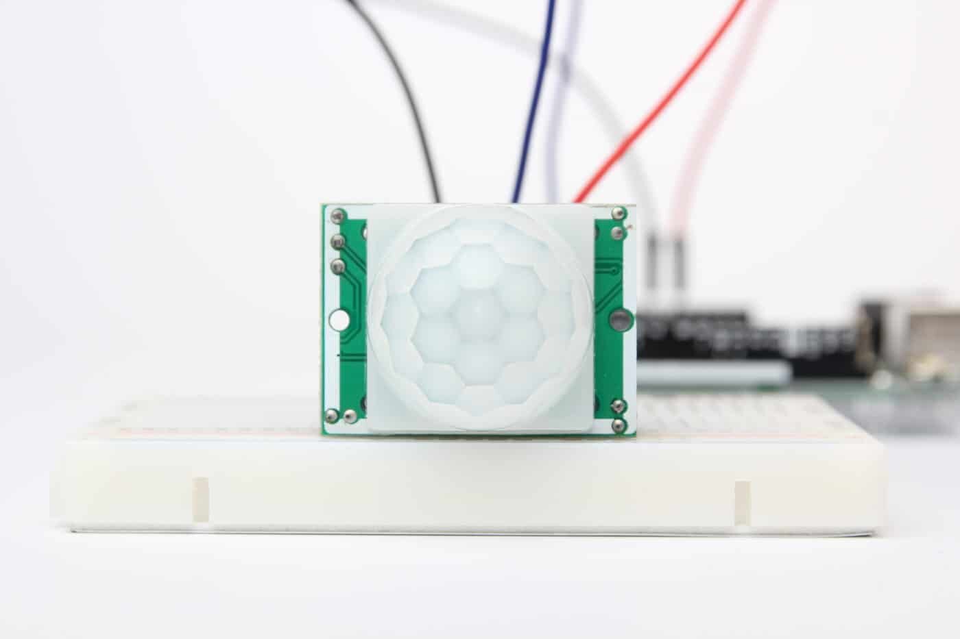
The white dome in front of the sensing element is a fresnel lens. This lens focusses the infrared radiation onto the sensor.
About the HC-SR501 PIR Motion Sensor
The HC-SR501 PIR motion sensor is built around the BISS0001 Micro Power PIR Motion Detector IC. This IC is specifically developed to process the signal from PIR motion sensors.
If you remove the fresnel lens, you will see the RE200B pyroelectric sensing element. On the PCB you can also find a built-in voltage regulator. This means you can power the board with a large DC voltage range, typically 5 V is used.
The specifications of the HC-SR501 are given in the table below, note that there might be small differences between manufacturers.
Unit - HC-SR501 Specifications
Operating voltage4.5 – 20 VQuiescent current50 μALevel outputHIGH 3.3 V / LOW 0 VTriggerL single trigger / H repeating triggerDelay time3 – 300 sBlocking time2.5 s (default)TriggerL single trigger / H repeating triggerMeasuring range3 – 7 m maximum2 mmMeasuring angle< 110° cone anglePCB dimensions32.5 x 24 mmMounting holes2 mm, 28.5 mm spacingFresnel lens dimensions15 mm x 23 mm diameterOperating temperature-15 – 70 °CCost